Dead reckoning. Types of analytical (written) notation
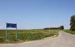
), which allows you to go directly to solving applied navigation problems in yachting. In this series of articles we will learn how to calculate the ship's path, draw it up on a marine navigation chart, and again, we will get acquainted with new concepts. Well, how could we do without this (I’m talking about concepts). To ensure safe yachting, the skipper needs to clearly navigate the environment and clearly know the place of your boat. In order to solve this problem, graphical constructions are performed on the map, reflecting the direction of the path, the values of compass courses, the values of bearings and distances taken, calculations for safe divergence from detected objects, etc. The entire complex of such constructions is called a navigation plot.
Before the transition begins, the yachtsman studies the entire range of navigation conditions for the upcoming yachting and plots the expected transition route and additional information on the map (raises the map). This is a pre-layout.
As soon as the yacht leaves, the navigator begins to carefully record the elements of movement, courses, speeds, and drift from the intended path. The navigational staff on a yacht usually means the captain. Who else, he is both a reaper and on the pipe... well, you understand. Although sometimes there are competent crew members (not organs) on the boat who can perform this task. However, I digress, let's return to our... accounting. The location of the vessel and elements of the influence of external factors (wind drift and current) are determined and plotted on the map. This is a performance gasket.
When the exact position of a yacht is not determined by navigational or other means, it is plotted on the chart using the course it is following, parameters of external influences (if determined) and speed. This is the dead reckoning method. The calculation of the vessel's path itself is carried out continuously throughout the entire passage and its data is corrected, if necessary, when the yachtsman receives an observation place. The dead reckoning system itself comes in two types: graphic and analytical.
Analytical dead reckoning of a ship's path.
Analytical dead reckoning of a ship's path involves calculating the coordinates of the yacht's location using formulas and known data and then plotting it on a map. This dead reckoning method is used mainly in ocean navigation when using small-scale maps. In modern yachting, this ship's dead reckoning system is not in great demand; nowadays only professional navigators are involved in it; GPS helps them. Therefore, we will not consider it in this article. But let’s look at the graphical dead reckoning of the vessel’s path in more detail, especially since it is intuitive and allows even a novice yachtsman to navigate the space without electronics (pah-pah-pah).
Graphic dead reckoning of the ship's path.
The method of graphical dead reckoning of a vessel involves drawing track lines on a map indicating courses and other data, taking into account drift (if its parameters are known). The essence of the difference between these two dead reckoning systems is that when analytically dead reckoning a vessel's path, the above complex of graphical constructions is not carried out, and therefore is difficult to master for a wide range of amateur yachtsmen. And who wants to sit in a cramped navigator’s seat and do arithmetic operations? Or do you do the same thing, the same activity, but drawing interesting lines and arrows on the map? The main thing is not to get too carried away with drawing and not to spoil the map, which you cannot do without in yachting.
The ship's position obtained only as a result of any dead reckoning method is called dead reckoning. Let us dwell for now on the concept of dead reckoning of a ship's path. To begin with, let’s assume that the yacht is not affected by any external factors (neither drift nor current). Then it is clear that the ship’s path will lie along the line of its course and it will cover a distance in a certain period of time equal to the product of its speed by the value of this period of time.
The path of the yacht, laid out on the map, is called the heading angle. The distance traveled by the boat is shown on the yacht's route. This distance can be theoretically determined by multiplying speed by time, but practically it is taken from the log readings, because The log counts exactly the distance traveled, and it already “calculates” the speed. At the start point of the graphical dead reckoning of the vessel's path, the time and lag count (T1 and OL1) are noted in the form of a fraction, the numerator of which is the time (accurate to the minute), and the denominator is the lag count (accurate to 0.1 nautical miles). This data is plotted on the map near each countable place (if there is an observation, at the observed place). The ship's course is plotted from the point of reference. Relative to this point, the remaining calculations and constructions are made. The frequency of plotting countable and observed points is determined by the captain’s decision, depending on the conditions and complexity of yachting.
Dead reckoning of a vessel, solving graphic problems.
Now that we have become a little familiar with dead reckoning and routing, we can move on to the direct solution graphic tasks. So let's get started. Using the available coordinates, we plot a numerable place on the map, from which we will carry out further construction (this can also be an observed place, there is no fundamental difference, only the designations are different).
In this case, let our initial data be: initial time 00.00; initial lag count 00.0; ship speed is 12 knots. It is clear that in practical sailing yachting no one goes at such a speed, but let’s not forget about “our smaller brothers” - motor yachts. And similar calculations are relevant for them too. Despite the fact that they lack an important component of true yachting - a sail, at sea they are subject to the same factors as sailing yachts.
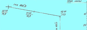 We draw a course line from this point using a parallel ruler and a navigator's protractor. Let the initial heading be 100°; the current and drift are not yet known to us, and therefore are not taken into account. And don’t forget to convert the compass heading value taken from the ship’s compass to the true one. One hour of yachting passes. The time will be 01.00. The lag count is 12.0. Let's mark this countable point on the map at 01.00. Next, in another hour, we will need to turn to a new course - 180°. But for now we will only mark the point at 01.00.
The time has arrived at 02.00. And we, as we needed, turned to a course of 180°. From the point corresponding to our moment in time, we will simply plot a new course. At the same time, we are still only conducting a graphical dead reckoning of the ship’s path. We don't have any observations. In another half hour we will turn to a new course of 225°. And now our lag count is 24.0. Let's calculate how much distance we need to put on the course line to get a countable point.
ROL (lag count difference) = 24 - 12 = 12 - set aside 12 nautical miles.
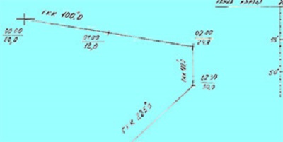 Don’t forget to write the rate value above the new rate line. In half an hour the time will be 02.30, and the lag count will be 30.0. We calculate the deferred distance again as stated above:
ROL = 30 - 24 = 6 - set aside 6 nautical miles, mark our reckoning point and plot a new course.
Now, let’s assume that we have the opportunity to accurately determine the location of our yacht, we will make an observation in 15 minutes. Accordingly, the time point will be 02.45, and the lag count will be 33.0.
Oops! But our observed point does not coincide with the countable one. What does this mean in our dead reckoning method? But you can’t say for sure right away. Not everything in yachting is so simple.
We can only assume that we have mistakenly determined the location of the yacht or that it is affected by either current or wind drift.
We can more accurately judge the cause of the discrepancy only by having several observations. Let’s analyze their position relative to the countable points and see what’s going on. To do this, we will continue to make location determinations every 15 minutes. In the drawing of our layout, the countable points and the observed ones next to them will be visible.
Please note that there is no wavy line (discrepancy) between the countable and observed points. This means that we did not take the observation into account and continue to conduct graphical dead reckoning of the ship’s path, assuming our place on the plotted course line. This does not mean that the observation itself is called into question. We’re just thinking for now, and the circumstances of yachting allow us not to take the observation point into account for now. When sailing, for example, in cramped conditions, we constantly determine the ship’s position and navigate by observations. But more on that later.
 Let's return to our map. We see that the observed points lie further and further from the countable ones. This is already a system. We look for reasons and begin analysis. The first thing we need to pay attention to is which line, straight or curve, our points are located on. If along a curve (some kind of hyperbole, for example - but, most importantly, along the correct curve), then we have every right to believe that the landmark used to determine the position of the yacht in our dead reckoning method has been incorrectly identified by us and we, taking values of navigation parameters (bearings and distances, for example) of one landmark, on the map we plot them from another. In this case, it is necessary to immediately identify the landmark(s) using all available means. (Don't forget about GPS control). If our points are located in a straight line, this means that some external (and, moreover, linear) factor is acting on the yacht.
Simply put, either the wind carries us away, or the current, or both. How can we determine this? In principle, it’s not difficult. In yachting you can always find a way out. There are two important rules to remember here:
The lag takes into account drift (at small drift angles).
The log does not take into account the current.
If you don't get too clever, it looks like this. We measure on the map the distances between two countable points and the observation points corresponding to them in time. If these distances are equal, then we are dealing with drift. The lag doesn't care, it takes drift into account. That there is no drift, that there is, the lag distance indicates (if it is in good order, of course) relatively correctly.
This is exactly the case in our case, that is, we are drifting. But if the distances between pairs of countables and the corresponding observed points differ, and the magnitude of this difference is constant, we are undoubtedly faced with the action of the current.
But in order not to overload this article and the brains of the thoughtful reader, we will talk about the influence of drift and current on the ship’s dead reckoning later, in.
Based on materials from the book "Basics of Navigation" by A.E. Seleznev
Graphic dead reckoning of the ship's path
The essence of graphical notation
Safety of navigation in terms of navigation is ensured the right choice route between points and following the chosen path.
Choosing a route is one of the most important tasks in navigation, the decision of which is based on a thorough analysis of the entire situation during the transition.
The selected route of the vessel is plotted on maps - preliminary plotting is performed. Preliminary laying is carried out before the vessel leaves for the voyage by the captain. It is the result of work on choosing the safe and most profitable route for the vessel. To ensure navigational safety of navigation, places of course changes are marked on the map, for which turning points are chosen so that the moments of the vessel's arrival at these points can be quickly determined, for example, the moments of arrival on the beam, on the target, etc.
They outline the distance at which capes, lighthouses, and other landmarks will pass.
The declination is given to the year of voyage and its value is written in pencil along the entire voyage of the ship.
The true course values are written above the track lines.
The distance in miles along each course is taken from the map and the number of miles of the entire passage is calculated.
On the route, the limits of the visibility range of beacons and lights for the height of the bridge are marked, and the most appropriate ways of determining the position of the vessel in individual areas are outlined. Time is kept from the operating time, counting the departure time of the vessel at 00 hours 00 minutes.
Before performing preliminary laying, the card is lifted (see § 45).
Calculations made during the preliminary laying process are approximate and must be adjusted during navigation.
Preliminary routing is carried out, as a rule, on route maps.
The second most important task– ensuring the movement of the vessel along the chosen path, for this purpose they continuously record the movement of the vessel – dead reckoning of the vessel’s path.
The main elements of dead reckoning are heading (by compass) and distance traveled (by log).
The graphical dead reckoning of the vessel is expressed in the conduct executive navigation pad. Its beginning coincides with the ship's departure from the pier (anchoring); when leaving the port, the navigator pays special attention to visual orientation in the surrounding environment, based on knowledge of the harbor or roadstead and the correct use of the navigation system, aids to navigation and natural landmarks.
Once in clear water, the vessel's position is precisely determined and the laying is carried out from the obtained point.
Before arriving at this point, turn on the lag, near the starting point, write down the time as a fraction in the numerator, and the lag count in the denominator.
An IR line is laid from the starting point, on which countable points are marked every hour or four hours, i.e. places obtained without measuring the navigation parameters of external landmarks.
Countable points are marked on the track line with a short transverse line, and the thickness of the track line itself should be approximately equal to the thickness of the meridians and parallels.
All laying and calculations are performed with a soft, finely sharpened pencil.
Locations of the vessel according to observations, i.e. Based on the results of measuring navigation parameters, external landmarks are plotted as often as possible and necessarily, if possible, when changing course.
Observed places are indicated by symbols in accordance with RShS-89.
The discrepancy between the observed point and the countable point is called a discrepancy, denoted by the letter “C”. Its direction and magnitude are recorded in the ship's log (С=225º -1.5’)
The direction of the discrepancy is calculated from the calculated point to the observed one.
The laying process ends when the vessel enters the port waters or at the point where maneuvers begin when the vessel is anchored.
Thus, a routing is a set of measurements, calculations and graphical constructions associated with choosing a ship’s path, taking into account its movement and determining the ship’s position.
Maintaining graphical notation and solution
tasks in the absence of drift and flow
The absence of ship drift and drift simplifies both graphical construction on the map and calculations when solving various problems.
Firstly, the ship's path coincides with the direction of its DP, i.e. with IR line.
Secondly, the distance traveled by the ship relative to the water i.e. according to the log readings, corrected by its error, it is at the same time the actual distance traveled relative to the ground (S L = S I).
Solution of the direct problem
(Course correction tasks)
|
With a given steering CC according to MK |
The same for the Civil Code |
||||||||
Solution of the inverse problem
(Tasks for course translation)
Solving specific problems
I.Plotting the ship's location on the map.
Given: T 1, OL 1, T 2, OL 2. Find: S L.
Purpose and types of notation. Main tasks
Solvable on the map
Reckoning is the process of obtaining the position of a ship at any moment based on its movement from a point taken as the starting point.
Dead reckoning forms the basis of navigational (instrumental) navigation. The captain's assistants perform the counting on a watch basis under his control during the entire voyage. They begin counting immediately upon leaving the port or lifting the anchor, and end with arrival at the roadstead of the port of destination. The place and time of the beginning and end of counting is determined by the captain. The most accurate position of the ship that can be obtained under the given conditions is taken as the starting point. If a large dead reckoning error is discovered during a voyage, then transferring it to a new starting point and changing the elements of movement taken into account are also done with the knowledge of the captain.
The position of the ship on the map obtained by dead reckoning and its coordinates j c, l c are called reckonable. Near such a point, a horizontal line is drawn, above which the ship's time is written (hours, minutes), and below - the log count (miles without indicating hundreds, tenths). If the log does not work, then a dash is placed below.
Retaining the essence of notation, it is divided into three types: graphic, analytical and automatic. Regardless of this, if necessary, they stipulate what conditions are taken into account - drift, current, circulation.
Countable points are supposed to be plotted on the map during any changes in the course and speed of the vessel, during other changes in sailing conditions, as well as during all events that are recorded in the ship’s log. If the course and speed are constant, then when sailing along the coast, countable points are plotted on the map every hour, and when sailing in the open sea (in the ocean) - after four hours when changing watches.
Usually the countable place is found at the current moment of the ship's time. Sometimes it is necessary to find the estimated countable place at a given moment in the future or, on the contrary, it is necessary to restore the countable place at the time of some event in the past. Similar and any other number problems can be solved graphically or analytically.
To graphically solve various navigation problems, they use a measuring compass, a parallel ruler and a navigation protractor.
A measuring compass is used to measure and plot distances on a map. Distances are measured in nautical miles. The scale is the side (vertical) frame of the map opposite the place where the measurement is made. One minute of this scale is equal to one nautical mile.
A parallel ruler is used to draw straight lines on a map parallel to a given direction. It consists of two rulers connected by metal rods on hinges. This connection allows you to move the ruler while maintaining a given direction, which is necessary when laying course and bearing lines. An ordinary drawing compass is also used, with the help of which arcs are drawn on the map - when determining a location by distances to coastal objects.
A navigation protractor is needed to plot and measure angles on a map. It is a graduated semicircle with a ruler centered at point "0". On its outer arc there are degree divisions. The division bars, multiples of five degrees, are elongated. Opposite the strokes marking tens of degrees are two numbers differing by 180°. The upper numbers correspond to the directions of the northern half of the compass card, and the lower ones correspond to the southern half. In order to draw a line on the map at a certain angle to the meridian, it is necessary to place a protractor on the map so that the central stroke “0” and the line on the arc, indicating a given number of degrees, coincide with the meridian line. Then a line drawn along the upper edge of the ruler in the appropriate direction will give the desired direction.
When laying, it is necessary to solve the following main tasks:
1) remove the latitude and longitude of a given point from the map;
2) use a given latitude and longitude to plot a point on the map;
3) plot a course or bearing from a given point on the map;
4) set aside a certain number from a given point in a given direction
5) determine the direction of the course or bearing marked on the map;
6) measure the distance between two points on a sea map;
7) plot a course on the map from the starting point at a given distance from
this item;
8) move a point from one map to another.
1. Take the latitude and longitude of a given point from the map. This problem is solved using a compass. Having placed one needle of the compass at a given point, move it apart so that the second needle falls on the nearest parallel. By drawing a part of the circle with a compass, make sure that its needle touches the nearest parallel at only one point. Then, without changing the solution of the compass, transfer it to the side of the map frame and, applying one of its needles to the same nearest parallel that touched part of the circle, and the other, directing it along the frame towards this point, i.e. to N or S from this parallel, take the latitude corresponding to this point.
To measure longitude, place one needle of a compass at a given point and, expanding it to the nearest meridian, use the second needle to describe a circle tangent to the meridian. Without changing the solution of the compass, transfer it to the lower or upper part of the map frame and, placing one of its needles on the meridian to which part of the tangent circle was drawn, place the second needle on this frame towards the given point and take the longitude.
Latitude and longitude are recorded with an accuracy of 0¢.1, if the scale allows.
2. Using the given latitude and longitude, plot a point on the map. To plot a point on the map, look for a division on the side frame that corresponds to the number of degrees and minutes of a given latitude, and, applying a parallel ruler to the parallel closest to this division, move the ruler so that one of its cuts falls on the division of the given latitude; then, in the rectangle where the point should approximately be located, a line is drawn between the two meridians along the cut of the ruler. Having found a division on the lower or upper part of the map frame that corresponds to the number of degrees and minutes of a given longitude of a place, and using a compass to take a segment from this division to the nearest meridian, lay this segment on a line drawn with a pencil from the same meridian and get the point you are looking for.
The same task can be accomplished using just one ruler. To do this, having found the given latitude on the side frame and applying the ruler to the nearest parallel, bring its cut to the given latitude, along which a short line is drawn with a pencil in the rectangle where the desired point is located. Then, having found a division corresponding to a given longitude on the lower or upper part of the map frame, apply a cut of the ruler to the nearest meridian and, moving the ruler, bring one of its cuts to the division of the given longitude, along which a short line is also drawn. The intersection of two drawn lines gives the desired point.
3. From this point on the map, plot a course or bearing. To solve this problem, use a protractor and a ruler. Before you begin solving the problem, you need to imagine the direction of a given course or bearing, i.e. in which quarter of the horizon this direction will be located. Having placed a protractor with an attached parallel ruler on the map so that the lower section of the ruler is approximately the given direction with the meridian, turn the protractor without moving the central stroke away from the meridian either to the right or to the left until the division of the protractor corresponding to the given course coincides with meridian.
Having achieved a match, remove the protractor and, bringing the cut of a parallel ruler to this point, draw a course line, drawing it with a pencil along the cut of the ruler. If the protractor ruler is located almost in the direction of the meridian at courses close to zero or 180°, then it is better to apply the protractor to the parallel and set it to reference the given course ±90°.
The inscriptions on the protractor divisions are made in such a way as to indicate the direction of course or bearing; so for courses directed to N, or upward, the corresponding inscriptions on the protractors are at the top, while for courses or bearings directed to S, or downward, the inscriptions are at the bottom.
4. Set aside a certain number of miles from a given point in a given direction. When solving this problem, it is necessary to remember that a nautical mile on a Mercator map is depicted as segments of varying lengths, depending on latitude.
The specified distance is taken using a compass on the side of the map frame from a latitude approximately corresponding to the latitude of a given point. This distance is taken to N from this point if the course is directed to N, or to S if the course is directed to S, and is laid off from this point on the line of the plotted course or bearing. If the value of a given distance cannot be measured with one solution of a compass, then this distance is laid off in parts, and each part is taken at the latitude corresponding to this part.
5. Determine the direction of the course or bearing shown on the map. By attaching a ruler to the course or bearing line marked on the map and attaching a protractor to it, bring the ruler together with the protractor to the nearest meridian, aligning the central stroke of the protractor with the meridian. The reading on the protractor will give the value (in degrees and fractions) of the course or bearing being determined. If the course or bearing direction lies in the NE or NW quarters, i.e. in the N direction, then the upper reading is taken on the protractor, but if the direction is in the SE or SW quarters, i.e. in the direction to S, then the lower reading is taken.
6. Measure the distance between two points on a sea map. When measuring the distance between two points, place one compass needle at one point, and the other at the second, and measure the distance between these points. Then the compass is moved to the side of the frame and the distance taken with the compass is determined in the latitude corresponding to the distance being measured.
If the distance between points cannot be measured with one compass solution, then it is measured in parts - each part in the corresponding latitude.
7. Plot a course on the map from the starting point at a given distance from the given object.
To solve this problem, remove a given number of miles from the side frame of the map, in that part of it that falls opposite the given object.
Place the needle of a compass on the map at the point corresponding to the location of a given object, and use a pencil of a compass to describe an arc.
From the starting point, draw a tangent to the circumcircle.
8. Move a point from one map to another.
This problem can be solved in two ways:
· take the latitude and longitude of a given point from one map and use them to plot the point on another map;
· take from one map the true bearing of some object marked on both maps, and, having measured the distance from this object to a given point, plot the taken true bearing on the other map and lay off the measured distance from the object on the bearing line, taking it on the scale of the second cards.
Wind accounting
Graphic dead reckoning (laying) consists of calculations and plotting on a map, which should reflect the movement of the vessel as accurately as possible.
A simple laying at a constant course, when there is no wind or current, is as follows (Fig. 1.15). On the map, from the initial (previous numeral or observed) point M o, draw a line of the intended path and measure the corresponding true course IR with a protractor. Above this line (it coincides in such conditions with the course line) the course according to the main compass is written, and its correction is written in brackets. This course and correction are rounded to the nearest half degree so that their algebraic sum gives IR (in Fig. 1.15 IR = 67.5°).
Based on the difference in the lag roll readings for the desired countable point M c and taken as the initial Mo (in Fig. 1.15 roll = 62.5), the vessel's navigation along the lag S = V roll is calculated using the formulas. This voyage is plotted on a map scale along the course line and a countable place M s is obtained. Such a place is marked with a dash across the course line and, as always, the ship's time and log count are inscribed. Of course, they don’t put on the map those shown in Fig. 1.15 designations IR, M o, S l and M s.
The ship is located on the border between air and water. When a ship moves, the movement of air masses (wind) deviates it from the intended course and changes its speed; In addition, the wind spreads the wave (which causes the vessel to yaw) and creates a drift current.
The wind gets its name from the point on the horizon from which it blows
If, for example, the wind blows from NE, then it is called NE.
It is customary to say: the wind "blows into the compass" A the ship "goes from the compass".
The angle between the direction of the wind and the centreline of the ship is called the ship's heading relative to the wind. If the wind blows to starboard, then they say that “the ship is sailing on starboard tack.” If the wind blows to the port side, then they say that “the ship is sailing on port tack.”
When the angle between the center plane of the vessel and the wind line is less than 8 points, or, for that matter, less than 90°, then they say that “the ship is on a close-hauled course”, adding the name of the tack: “hauled course of the starboard tack” or “ close-hauled course on port tack.”
The left tack is abbreviated as l/g, and the right tack is abbreviated as p/g.
The close-hauled course can be steep and complete.
A close-hauled course will be when the angle between the center line of the vessel and the wind direction is less than 6 points. If this angle is more than 6 points, then in this case the course is called full close-hauled.
When the angle between the center plane of the ship and the wind line is 8 points, or 90°, then the ship's course is called galfind, or half the wind (Fig. 1.16.).
When the angle between the center plane of the vessel and the wind line is more than 8 points, but less than 16 points, then the course relative to the wind is called the backstay (Fig. 1.16).
When the wind blows directly astern, the ship's course is called jibe.
When the wind blows directly into the bow of the ship, they say: “the wind is blowing straight across the bow” or “the ship is going against the wind” (leventik).
While the ship is moving, a stream of water remains behind its stern, called the wake. When heading gybe or left, the center plane of the vessel coincides with the wake.
On other courses the ship is blown into the wind; such drift is called drift. During drift, the diametral plane makes an angle with the wake jet, which is called the drift angle (Fig. 1.17.).
Thus, the drift angle a is the angle made by the center plane of the vessel with the direction in which it actually moves in the presence of wind (path-drift or track angle with drift PU a)
Sailing ships have the greatest drift when heading close-hauled. Vessels with a mechanical engine, on the contrary, have the greatest drift during galfind courses, i.e. when the wind blows perpendicular to the side.
In general, the magnitude of the drift depends on various reasons. For example, the greater the freeboard, the less the vessel's draft and the stronger the wind blows, the greater the vessel's drift.
Under equal conditions, a deep-draft vessel will have less drift than a shallow-draft vessel.
The amount of drift on sailing ships can reach up to 1-2 points and even more. With a large stroke, the drift will be less than with a small stroke.
The amount of drift can be determined using the azimuthal circle of the compass, for which the direction finder is installed in the direction of the wake stream, thus obtaining on the azimuthal circle the angle between the center plane of the vessel and the line of its movement, in some cases formulas are used, but the most reliable measurement of the drift angle is obtained according to observations.
As can be seen from the definitions to Fig. 1.18, fair
![]() .
.
However, the main task is to follow the intended path. To do this, with the appearance of drift, you need to change the course by an angle a in the direction of the wind, as they say “take to the wind.” In this case, using the formula we find
![]() .
.
The resulting true heading is converted into compass KK = IR - DK and is given to the helmsman or set on the autopilot.
Reckoning, taking into account drift, is carried out along the track line, postponing the navigation S l on it, designating and labeling the points to be counted as in the simplest laying. To obtain the vessel's position abeam any landmark, its bearing IP ^ = IR ±90° is carried out by notching on the track line.
The inscription on the map above the track line is made as shown in Fig. 1.18 with the calculation that the algebraic sum of the compass course, its correction and drift angle gives PU a, plotted on the map.
Wind waves cause the ship to yaw on course, especially when the wave bearing makes an acute angle with the ship's DP; The “yaw angle ¡” can reach £ 4°, and due to the complex interaction of the wind with the superstructure and the wave with the hull, the sign ¡ can become opposite to the sign of the angle a and larger in magnitude, i.e. the ship will not go downwind, but to the wind: for example, a = +2°. ¡ = -3°; total effect (a + ¡) = -1° (with port tack wind the ship moves to the left!).
In conclusion, let’s consider a question that is specific only to a sailboat:
If a sailing vessel needs to reach a target “upwind”, i.e. to go against the wind, it is necessary to use tacking, i.e. tack towards the wind (Fig. 1.19.).
The turning point (change of tack) is located at the moment when the object is at a speed equal to twice the optimal tacking angle plus a (optimal tacking angle = angle of greatest climb when moving into the wind).
Accounting for current
For various reasons, water in the seas and oceans has a forward movement, which is called a current.
A current has two elements: speed and direction. The speed of the current is the number of miles that water particles travel in an hour. When the current is weak, its speed is determined by the number of miles per day.
The direction of the current is taken to be the direction in which a floating object moves away from the observer solely under the influence of the current alone.
Usually the direction of the current is indicated in true bearings and gets its name, like the course of the ship, from the point on the horizon to which it is moving. It is customary to say about the direction of the current that the current, like the ship, comes from the compass.
Currents can be constant, periodic (tidal) and random.
Constant currents are those whose direction and average speed remain almost unchanged from year to year. The speed of the current varies and ranges from 10 to 120 miles per day.
Tidal currents are those currents that arise from the action of tides.
Tidal currents reach significant speeds in some areas (£15 knots)
Random currents occur as a result of winds blowing for a long time in the same direction, as well as from rains that last for a long time, etc.
Everything said earlier in this section about dead reckoning allows us to take into account the movement of the ship only relative to the water. Obviously, to ensure navigational safety, it is also necessary to take into account the current.
The current velocity vector V t is characterized by its direction relative to the meridian K t and the speed V t. Let us denote the vector of the relative speed of the vessel V c, and the vector of its absolute (relative to the shores and bottom of the sea) speed, which is also called the track speed V p. According to the meaning of the named speeds, we have the following vector equality:
If the relative speed V c and the ship's course IR = KK + DK, the drift angle a and the current vector V T are given, then in order to find out where the ship is going and at what speed, it is necessary to solve the vector equality. To do this, first find, as described in the previous paragraph, PU a and lay a path line without taking into account the current. Vector V c is constructed along this line, and vector V T is constructed from its end (Fig. 1.20). The closing vector V p gives the launcher's track angle, ground speed, and also reveals the drift angle b. This angle is considered positive when drifting to the right, and negative to the left. From definitions and Fig. 1.20 see
![]() .
.
The track angle PU c determines the direction of the vessel's track line, above which are inscribed, as before, KK, DK and the total drift angle c = a + b. Countable points are plotted on the same line, but the navigation S l is postponed along the line PU a, from where the notches are transferred to the path line PU c parallel to the vector V T (see Fig. 1.20).
If the action of the vector and current is assessed from observations, for example, from precise observations, then the drift angle is obtained With between the lines of the true course and the ship's path
![]() .
.
The drift angle c is the angle between the bow of the center plane of the vessel and the vector of its ground speed V p. The drift to the right is considered positive, and to the left - negative.
More often in practice, the main problem of laying, taking into account drift and flow, is usually solved in a different formulation. Namely, the given path is the path along which the ship must move despite the action of wind and current. The drift angle a and the current vector V T are known. A graphical solution to this problem is performed as follows.
On the map, from the initial radix point, draw a line of a given path, which makes the angle PU relative to the meridian (Fig. 1.21). From the same point, a flow vector V T is constructed using its elements K t and V T, and from the end of this vector a notch is made on the path line with a compass solution equal to V c. This reveals the ground speed V p, the track angle of the launcher a and the drift angle b by the current (see Fig. 1.21).
Of course, instead of a vector triangle of speeds, the sides of which express the number of miles per hour, you can build a similar triangle of distances S = Vt for the same time interval t.
Countable points, as always, are plotted on the track line, for which the navigation S l is plotted along the line PU a and carried parallel to the vector V T onto the track line.
The ship is affected by the total (or total) current, the direction and speed of which are often known with large errors. If necessary, the direction K T and the speed V T can be determined by the “navigation” method using observations: with a sufficiently accurate account of the wind, K T is equal to the average value of several directions of discrepancies, and V T is the average value of several discrepancy values reduced to the hour of sailing.
During the voyage, the navigator must pre-calculate the time and (sometimes) the timing of the lag for the occurrence of various events: traverse, the shortest distance to a landmark, the opening of a lighthouse fire, a reporting point, etc. For each event, a point is marked on the map, and the time T and the countdown of the lag OL are found according to the formulas (Fig. 1.22.):
; ![]()
![]() ; .
; .
In Fig. 1.22 S p and S l are shown for the lighthouse abeam, OIP ^ = IP ^ ±180°, IP ^ =IR ±90°.
Circulation accounting
Circulation is the trajectory of movement of the ship's center of mass with a constant rudder laying.
To take into account when laying, the circulation of small and medium-tonnage vessels is taken as an arc of a circle with a radius R c (half the tactical diameter) and a time t 180 for turning by 180°. These agility characteristics are determined from field observations, usually with two rudder positions: half on board - 15° and on board - 35° for a loaded and unladen vessel.
If the course lines before and after the turn are specified on the map, then the circulation is constructed as follows (Fig. 1.23). Draw a bisector MO of the angle of intersection of these lines and find a point O on it, from which an arc of radius R c is tangent to them. This determines the starting point H and end point K of the turn.
The time of rotation through angle a (in degrees) is estimated using the formula
![]() .
.
In other cases, if the starting point H of the turn and the direction are specified
lines of the new course, taking into account circulation when laying is performed differently (see Fig. 1.23.).
From point H, a perpendicular HO is restored to the line of the previous course, a radius R c is plotted along it, and an arc with this radius is drawn from the resulting center O. Then, using a protractor and a parallel ruler, draw a new course line tangent to this arc, which determines the end point K.
The same points H and K for a given R c and rotation angle a can be obtained by calculations and construction of segments d 1 and d 2 or angle q and segment d.
Intermediate voyage heading angle ![]() , intermediate float value
, intermediate float value ![]() .
.
The arrival of the vessel at the initial point H should be pre-calculated based on time and lag counting. It is even more important to outline the secant bearing and distance of the landmarks for arriving at this point. The approach to the new course line must also be controlled using predetermined bearings and reference distances.
S T = V T. t a;
The direction of the segment S T is laid from point H in the direction opposite to the flow, the rest is obvious from the figure.
When sailing, the ship is on the border of two environments - air and water, the movement of which affects it, deviating it from course and changing its speed.
The movement of a ship by the wind is called drift. Wind is the forward movement of air masses. The wind direction is the direction (in degrees) from which the wind is blowing. Wind speed is measured in meters per second or points.
Fig.1
Let V0 be the speed of the ship relative to the water, due to the operation of its own propulsors (Fig. 1). Air resistance to the movement of the ship is perceived by an observer on the ship as a counter flow of air, the velocity vector of which is (-V0). Let u be the true wind speed vector. The oncoming flow of air and the true wind, adding up, form a total flow observed on a moving ship and called the apparent (observed) wind. The apparent wind speed vector is equal to the geometric sum:
W = u + (-V0) = u - V0.
The apparent wind speed is determined automatically using an anemometer or manually using an anemometer, the KW direction is determined by an anemometer or in the direction of a flag or pennant. Apparent wind. Without acting on the ship at a heading angle qW, it causes a total aerodynamic force P applied to the center of the ship's sail. Due to the refractive properties of the superstructure, the direction of action of the force P in the general case does not coincide with the direction of the apparent wind. Under the influence of force P, the ship moves in the direction of this force with a drift speed VDR.
Let us decompose the velocity VDR into components VDR X along the center plane and VDR Y along the beam. The speed VDR X, depending on the direction of the apparent wind, is subtracted or added to the speed V0. If the lag works, it takes this speed into account. That's why
Vl = V0 + VDR X.
The speed VDR Y deviates the ship from the given course. By geometrically adding the speed of the ship Vl with the speed VDR Y, we obtain the vector V of the actual, or ground, speed of the ship:
V = Vl + VDR Y.
As you can see, when adding the velocities Vl and VDR Y, the ship moves in the direction of their resultant.
The line along which the ship actually moves relative to the bottom of the sea under the influence of propulsion and apparent wind is called the drift line. The diametral plane of the ship, when moving along the track, remains parallel to the true course line. This is due to the fact that the helmsman constantly maintains a given true course. Consequently, the ship moves along the track forward not with its bow, but with its bilge.
The angle in the plane of the true horizon between the northern part of the true meridian and the track line during drift is called the track angle during drift of the PU?.
The angle in the plane of the true horizon between the lines of the true course and the path during drift is called the drift angle?. If the wind is blowing to the left side of the ship, the drift angle is positive (the heading angle during drift is greater than the true heading). When the wind is from the starboard side, the drift angle is negative (the track angle during drift is less than the true course).
The drift angle depends on the speed and heading angle of the apparent wind, on the speed and design features of the ship: the height and architecture of the superstructures, the surface of the hull and the shape of the hull contours. The drift angle is measured using a drift meter. In the absence of this device, drift angles for various sailing conditions are selected from a drift table compiled from experimental data. From Fig. 1 visible:
Formulas - algebraic, angle? comes with his sign.
In the practice of navigation, one has to solve mainly two problems related to the drift of a ship. Direct task:
Calculate the track angle when the launcher drifts? (the line of the ship's path when drifting), if the true course is specified.
To solve this problem you need:
— determine the sign of the drift angle?;
— calculate the heading angle qW of the apparent wind;
— choose the angle size? from the drift table by arguments: by ship speed and qW;
— calculate the track angle when the launcher is drifting?, draw a track line on the map.
CC = 79.0°; Vl = 12.0 knots;
?GK = + 1.0°; wind 5° -12 m/s.
Solution:
The wind is blowing to the left side of the ship - angle? positive:
IR = CC + ?GC = 80.0°;
? = +4.0°; PU? = IR + ? = 84.0°.
2. Laying true radio bearings if the radio beacon is located outside the eastern or western borders of the map frame.
To find the position of the defining point (point M’) through which the radio bearing will be carried out on the KRMK (point A), it is necessary:
1) ? from “RTSNO” write down the coordinates of KRMKA (?A, ?A);
2) ? calculate the value? ? = ?P – ?A, where?P is the longitude of the side frame of the map;
3) ? draw a parallel to KRMKA on the map (?A– from “RTSNO”) and plot the segment;
4) ? through point A" draw the additional meridian aa;
5) ? from point A’ carry out Lock. P KRMKA A to the intersection with aa - t. M;
6) ? from point M along aa, set aside a segment and, through the resulting point M’, carry out a radio bearing on KRMK A? this will be the desired position line (I–I).
Laying carried out without checking the position of the vessel by determining its place by shore objects or by heavenly bodies, called dead reckoning .
Calculus performed on a map using the graphical construction method is called graphic dead reckoning of the ship's path.
performed using calculations using special formulas - written(analytical).
Graphical notation. The essence of this method is as follows.
At the moment of determining the starting point “a”, note the time on the ship’s clock (up to 1 minute) and the readings of the log counter (up to 0.1 miles). The starting point “a” is circled and an inscription in the form of a fraction is made near it in an empty space: numerator - time , denominator - lag readings 18.00/2.5 If the observed point a" is sufficiently close to the starting point a, then from point a" a first course line is laid in the form of a straight line parallel to the line ac. After this, the AC line is erased from the map, and on the newly drawn line the number of degrees of the compass course is written and next to it, in parentheses, the general compass correction AK calculated for this course, so that you can always determine which course you were following.
Maintaining a graphic plot allows the navigator to have a clear idea of the vessel’s position in relation to navigational hazards.
A vessel with operating propulsors, in the absence of wind and current, moves along the IR line, and a vessel affected by the wind moves along the PU α line.
If a moving vessel is simultaneously affected by both wind and current, then it moves along the line Pu s.
![]() The direction of movement of the vessel under the simultaneous influence of wind and current is determined by the angle of the launcher with
The direction of movement of the vessel under the simultaneous influence of wind and current is determined by the angle of the launcher with
Direct problem: simultaneous consideration of drift and flow
-GK is given and you need to find PUs
1. On the map we draw a line IR (3cm) IR=GKK+∆GK
2. First we take into account the wind α=7˚ IR=300˚ (this means the wind blows to the left, which means α=-7)
3. We consider Puα=IR+(-α)=293˚ (from the starting point we draw the line Puα)
4. You need to construct ∆ speeds; for this you first need to find the relative speed. We have Vlag.(11 knots) AND ∆lag.=+9% (1.09); V0=Vlag.*coefficient L
V0= 11*1.09=12 knots
When doing joint accounting, we work on PUα
Now we put these 12 nodes on PUα and from the end of this vector we put Vcurrent. (from the condition 3.5 knots, 155˚)
5. From the starting point, draw the line Pus through the end of the current vector (long) and measure the degree of this line (284˚)
6. Find the total drift (c) β=Pus-Puα=-9˚ c=α+β=-16˚total. Demolition.
7. From our starting point we apply a bearing, we have GKP = 263˚, convert it to true IP = GKP + ∆GK = 262˚ (we apply this bearing)
8. On this bearing we make a notch at 14.3 miles (from the condition to the tower) and from this point (tower) we draw a lane. Until PUs
9. From the point on Pus (where the lane was drawn), parallel to the current, we draw a line to Puα and now we know the distance traveled by the ship on Puα. S=15 (let's say)
10. We count ROL Rol = ; Now we are looking for ol2 (aka ol traverse) OL2 = OL1 + ROL.